DUAL-VIEW ISPIM IMAGING
PROJECT COLLABORATORS
PUBLICATION
PROJECT BRIEF
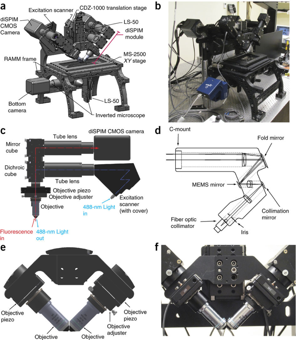
(a) Perspective view of assembled diSPIM, with microscope frame, inverted microscope components, cameras and major diSPIM subassemblies indicated. 'DiSPIM module' refers to scanners, dichroic filter cubes, tube lenses, objectives, piezos and associated optomechanics that move as a single unit on an LS-50 translation stage. Refer to the MATERIALS section for further description of component parts. (b) Photograph to accompany a. (c) Higher-magnification view of excitation and detection subassemblies in the diSPIM module. Excitation (blue) and emission (red) along a single arm of the module are highlighted. (d) Detailed view of the excitation scanner, showing fiber input, mirrors and relay lenses. (e) Higher-magnification view of objectives, piezos and holders/adjusters. (f) Photograph to accompany e. See also Supplementary Note 1, SF2 and SF3.
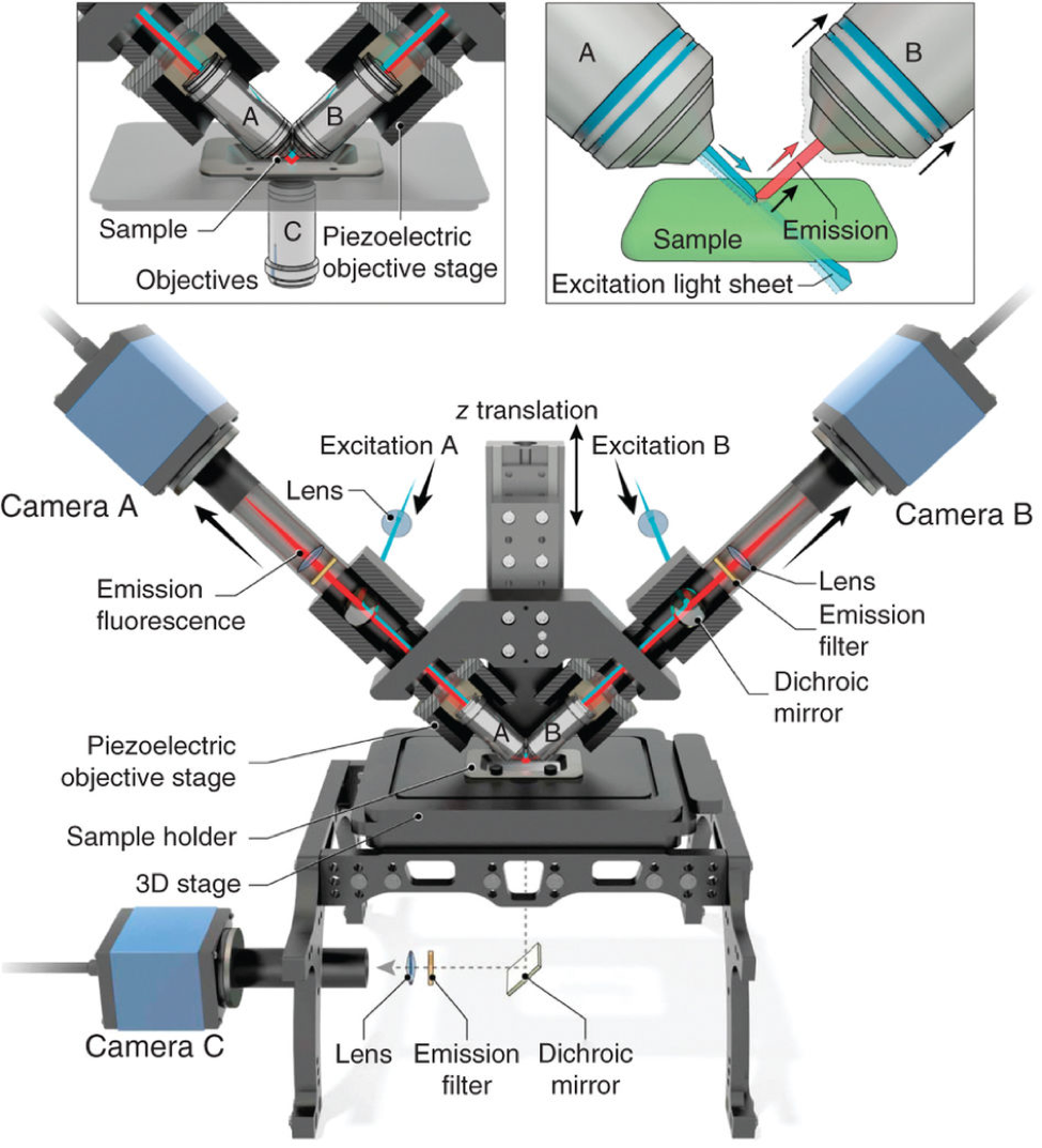
0.8 NA water-immersion objectives (A/B) are mounted orthogonally onto a z translation stage that is bolted directly onto the illumination pillar of an inverted microscope. In conjunction with other optics (Supplementary Fig. 1), both objectives produce a light sheet at the sample. Excitation A(B) occurs via objective A(B), and the resulting fluorescence is collected through perpendicular objective B(A), and imaged onto camera B(A) by means of dichroic mirrors, emission filters and lenses. Excitation (blue) and detection (red) are shown occurring simultaneously along both light paths in the lower schematic, but in reality volumetric imaging occurs sequentially as shown in the upper right inset. During acquisition, sample and objective A(B) are held stationary, the light sheet is scanned through the sample using galvanometric mirrors (not shown), and a piezoelectric objective stage moves objective B(A) in sync with the light sheet, ensuring that excitation and/or detection planes are coincident. The sample is mounted onto a rectangular coverslip that is placed onto a 3D translation stage, ensuring correct placement relative to objectives. The sample may also be viewed through objective C (see upper left inset), dichroic mirror, emission filter, lens and camera C placed in the conventional light path of the inverted microscope. This objective is particularly useful in finding or screening samples.